

Sizing a Fuel Polishing System: Flow Rate, Tank Volume and Turnover
How is a fuel polishing system sized?By turnover, which is how long the system takes to process a volume equal to the whole tank, and how often it does so. Flow rate on its own says nothing: the same pump is generously sized on a small tank and useless on a large one. The calculation is simple, but it only holds if the fuel actually circulates, which is a question about where the suction and return sit in the tank rather than about the equipment.
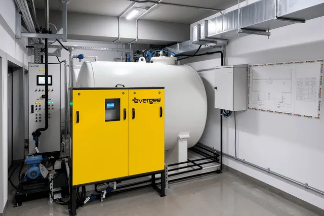
Turnover is the number that matters
The basic figure is a single division.
Tank volume ÷ flow rate = the time for one turnover
A 20,000 litre tank with a system running at 2,000 litres per hour takes ten hours to process a volume equal to its contents. That is one turnover.
One turnover is not one cleaning. Fuel returning to the tank mixes with fuel that has not yet been processed, so a single pass treats most of the tank partially rather than part of it completely. Getting a tank genuinely clean takes several turnovers, and keeping it clean takes a repeating cycle.
This is why flow rate quoted on its own is close to meaningless. Two thousand litres an hour is a comfortable specification on a 20,000 litre tank and an inadequate one on a 200,000 litre tank, where the same pump needs a hundred hours for a single pass.
What a sensible turnover interval looks like
There is no single correct interval, because the right answer depends on how fast the tank is degrading its contents. What follows is the reasoning rather than a rule.
| Situation | Turnover thinking |
|---|---|
| Temperate climate, clean tank, fuel turned over by use | Occasional processing is enough; the fuel is being replaced faster than it degrades |
| Standby set, temperate, fuel resident for months | A full turnover every week or two keeps water and particulate from accumulating |
| Standby set, tropical or Gulf conditions | The degradation mechanisms run continuously and faster, so a shorter cycle is justified |
| Known contamination being recovered | Continuous running over days, then back to a maintenance cycle |
The logic is the same each time. Set the cycle against the rate at which the tank generates problems, not against a number carried over from another site. A tank that breathes humid air every night accumulates water every night, and a monthly cycle leaves it accumulating for twenty-nine of those nights.
What pushes the flow rate up
Four things justify a larger system than the volume alone would suggest.
Contamination recovery rather than maintenance. A system specified to hold a clean tank clean is undersized for cleaning up a dirty one. If the tank has an established water layer and microbial growth, the initial recovery is a different duty, and it is worth deciding at the specification stage whether the permanent system is expected to perform it or whether recovery is a separate exercise.
Biodiesel content. FAME holds more water, oxidises more readily and supports microbial growth better than mineral diesel. Where EN 590 fuel with up to 7 per cent FAME is what the site will actually receive, the tank generates problems faster and the cycle should be shorter to match.
Climate. Warm fuel holds more dissolved water and drops it out on every cool period, and warm water grows organisms quickly. The same tank in Kuala Lumpur and in northern Europe does not present the same duty.
Tank geometry. A long horizontal tank, a tank with internal baffles or a tank with a large surface area relative to its volume all resist being circulated as a single body. That is a sizing input, not an installation detail.
The part that invalidates the calculation
A polishing system draws fuel from one point and returns it to another. If those two points are close together, the fuel goes round a short loop and the rest of the tank is never touched. The flow meter reads correctly, the filters stay reasonably clean, the reports look fine, and the far end of the tank is untreated.
This is the most common way a correctly sized system fails to do its job, and no amount of extra flow rate fixes it.
Three things prevent it:
- Draw from the low point, where water and sediment actually collect, rather than from a convenient mid-level connection.
- Return at distance, at the opposite end of the tank from the suction, so the returning fuel has to travel through the contents to get back.
- Return in a way that promotes movement rather than simply discharging near the surface, so that the tank contents are stirred gently rather than stratified.
On a long horizontal tank, more than one suction point is sometimes the honest answer. That is a cost decision, and it is better taken at design than discovered at commissioning.
Filtration stages, and what each is for
Sizing the flow is half the specification. The other half is what the fuel passes through.
A typical arrangement handles three things in sequence: bulk water separation first, so that the free and coalesced water is removed before it reaches anything finer; then particulate filtration, staged so that coarse material is caught before the fine element; then the fine element itself, which is what determines the cleanliness of the returned fuel.
Two practical points follow from that order. Putting a fine filter in front of the water separation stage wastes elements, because water and biomass blind a fine element quickly. And a differential pressure gauge across each stage is what tells you which stage is working and when an element is loading, which is the information that makes the system maintainable rather than mysterious.
Duty cycle: continuous or scheduled
Both approaches work, and they suit different installations.
Continuous running at a low flow rate keeps the tank contents in permanent slow circulation. It suits large tanks and aggressive climates, and it produces a steady, boring trend that makes a change easy to spot.
Scheduled running at a higher flow rate processes the tank in defined windows. It suits smaller installations, it draws power only when running, and it maps neatly onto a maintenance regime.
What matters more than the choice is that the cycle is driven by the system rather than by an operator, and that the result is visible. Bringing the polishing duty, the differential pressures and the water alarm into the BMS or SCADA platform turns a piece of plant that runs quietly in a corner into a reading that the operations team can act on.
Specifying it, in the order the questions arise
- Tank volume and geometry. Volume sets the turnover arithmetic; geometry decides whether it is achievable with one suction point.
- Fuel and climate. Biodiesel content and ambient conditions set how fast the tank degrades its contents, and therefore how often it needs processing.
- Condition now. Clean tank to be held clean, or a contaminated one to be recovered. These are different duties.
- Turnover interval. Chosen against the degradation rate, not copied from elsewhere.
- Flow rate. Falls out of volume and interval. This is an output of the process, not the starting point.
- Filtration stages. Water separation, then staged particulate, with differential pressure visible on each.
- Suction and return positions. The detail that decides whether any of the above is real.
Done in that order, the flow rate is the sixth decision rather than the first. That is the practical difference between a system sized for a tank and a system sized for a catalogue.
Size a polishing system by turnover, not by flow rate: tank volume divided by flow gives one pass, and a clean tank needs several. Set the interval against how fast the tank actually degrades its contents, then place the suction at the low point and the return at distance, or the calculation describes a loop rather than a tank.
Standards referenced: EN 590 Automotive fuels. Diesel, for FAME content; ASTM D975 Standard Specification for Diesel Fuel; ASTM D6217 for particulate contamination by laboratory filtration; NFPA 110 for emergency and standby power systems. Read more on Diesel Fuel Maintenance Systems.